Basics of Memory Circuit – S-R Latch
Lab: Basics of Data and Program Circuitry
Video Runtime: 04:41
Let’s talk about how memory works. If you’re geeky, then this episode is for you. You’ll look at the S-R Latch as it handles the basics of the memory circuit.
Your key takeaways in this episode are:
- The S-R Latch is a flip-flop circuit
- Uses 2 NOR gates
- The S-R Latch is one bit of memory
- Set is “true” -> stores 1
- Reset is “true” -> stores 0
Study Notes
We’ve been talking bits, bytes, 1s, 0s…but how does a computer actually retain memory? It retains memory one bit at a time, using an S-R Latch.
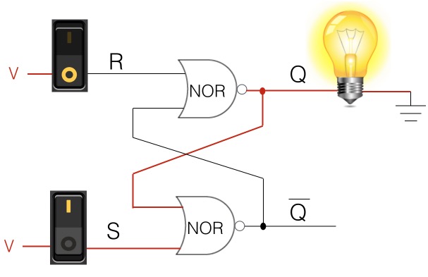
Imagine we have the gate circuit shown below. Let’s look at what is going on. We have:
- Two switches. We use these pictures of toggle switches because we’re used to seeing them and they help us visualize the “state” of something. These switches are actually outputs coming from other gate circuits, located upstream.
- Two NOR gates
- S (set) NOR gate
- R (reset) NOR gate
- Q-bar: on the S side, we have Q-bar
- Q: on the R side, we have Q, which is the opposite state of Q-bar
Set Memory

Now let’s walk through what’s happening in the wiring above.
- On the S side, we have power going through the switch and into the S NOR gate (so we have a 1.) Since the other input to the S NOR gate is also on (another 1), when the output goes through the inverter, it becomes a 0.
- The output from this S NOR gate (0) becomes an input to the R NOR gate. (Note: Since the output from the R NOR gate is an input to the S NOR gate and vice-versa, it is called a flip-flop.)
- So the R NOR gate receives that input (0) from the S NOR gate, and since the power going through the switch and into the R NOR gate is also a 0, that means both inputs are 0s. When the output from the R NOR gate goes through the inverter, it is changed to an on state, or 1. (This is where the S NOR gate gets its second input that we mentioned in Step 1 above.)
- Q is where the memory is being stored. In this particular diagram, Q stores one bit of memory, and its value is a 1. (The light bulb here is only used to help with visualization.)
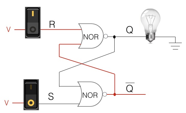
Reset Memory
During the reset, the circuit is storing a 0, which resets the memory state held in Q.

NOR Gate Cheatsheet
Remember your NOR Gate cheat sheet? Here it is again, in case you need a refresher after reading about the wiring above.
NOR Gate
| Switch 1 (in1) | Switch 2 (in2) | Light bulb (out) |
|---|---|---|
| 1 | 1 | 0 |
| 0 | 1 | 0 |
| 1 | 0 | 0 |
| 0 | 0 | 1 |
You will grow in this profession when you incrementally and systematically stretch yourself....bit-by-bit.
Episodes
Total Lab Runtime: 01:53:22
- 1 Lab Introductionfree 02:20
- 2 Understanding Switch Logicfree 13:36
- 3 Introduction to Pseudocode and Truth Tablesfree 16:28
- 4 Understanding Gates – NOT Gatefree 10:10
- 5 Understanding Gates – AND Gatefree 15:07
- 6 Understanding Gates - OR Gatefree 10:33
- 7 Understanding Gates – XOR Gatefree 10:42
- 8 Understanding Gates – NAND Gatefree 07:10
- 9 Understanding Gates – NOR Gatefree 06:34
- 10 Basics of Memory Circuit – S-R Latchfree 04:41
- 11 Basics of the Adder Circuitfree 16:01
