Basics of the Adder Circuit
Lab: Basics of Data and Program Circuitry
Video Runtime: 16:01
How does the computer do addition? It uses the Adder circuits which are the Half Adder and Full Adder.
Your key takeaways from this episode are:
- Half Adder
- adds 2 bits
- holds a carry bit
- but, it can’t add the carry bit from the previous column
- Full Adder
- adds 2 bits plus the carry bit for a total of 3 bits
- capable of adding the previous column
Study Notes
We’ve come a long way in this lesson. Here’s a brief recap:
- We’ve taken a look at the different types of gate circuits.
- We then combined those circuits together to form other circuits.
- We looked at how a computer stores memory in just one byte of data by using a combination of these gate circuits.
Your computer really does one very basic and elementary thing: it adds two numbers together.
Have you ever wondered how it does that?
In this topic, we’re going to talk about the basics of the adder circuit. We will review truth tables, and also look at them in a different light.
Half Adder
Let’s start with the half adder.
- It has 2 inputs: input 1, input 2
- It has 2 outputs: sum, carry
| AND | 0 | 1 |
|---|---|---|
| 0 | 0 | 0 |
| 1 | 0 | 1 |
| XOR | 0 | 1 |
|---|---|---|
| 0 | 0 | 1 |
| 1 | 1 | 0 |
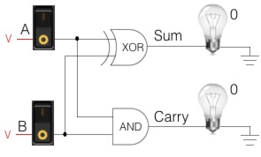
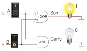
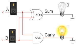
The Sum and Carry tables are read just like the condensed truth tables. Row 1 = input 1, column 1 = input 2, their intersection = output.
To solve a problem, first find the output by plugging your inputs into the Sum table.
| Sum | 0 | 1 |
|---|---|---|
| 0 | 0 | 1 |
| 1 | 1 | 0 |
Then, plug those same inputs in to the Carry table to determine if you have a carry bit.
| Carry | 0 | 1 |
|---|---|---|
| 0 | 0 | 0 |
| 1 | 0 | 1 |
Let’s test what we’ve learned and use the Sum and Carry tables to solve a problem: 7 + 2 = 9.
Binary Addition Lesson Refresher
You learned about binary addition back in Binary Addition.
In binary, this addition problem equates to: 0111 + 0010 = 1001. The table below will help you visualize this problem.
- We start at the LSB for 7 (0111) and 2 (0010) and plug those numbers into the Sum table. The LSB for 0111 is 1, and the LSB for 0010 is 0.
- At the intersection of 1 and 0 in the Sum table we find a 1.
- Bring this 1 down to the output row.
- Now we plug those same LSBs (1,0) into the Carry table.
- At the intersection of 1 and 0 in the Carry table, we find a 0. This means we have no carry bit.
- We are done with the LSB. Move one column to the left and repeat this process. In this column, our inputs are 1 and 1. From the Sum table we find a 0 for our output row. In the Carry table, we find a 1. Bring this 1 into the carry bit row for the column to the left of our inputs.
- We repeat this process until we compute the MSB column. Our output row shows the answer to our problem: 1001.
| carry bit | 1 | 1 | ||
|---|---|---|---|---|
| 7 (input 1) | 0 | 1 | 1 | 1 |
| 2 (input 2) | 0 | 0 | 1 | 0 |
| output | 1 | 0 | 0 | 1 |
Limitations of the Half Adder
In the above addition, when a carry bit occurs, the Half Adder stores it into the Carry Out for the next column to process. But look at the inputs to the Half Adder. It cannot accept a carry bit into it, rather, only the two inputs. This is the limitation of the half adder. It can only add two inputs and not the carry bit.
Full Adder
We’ve identified a limitation with the half adder: it can only add two bits. It can’t handle the carry bits.
We need a way to process the carry bit. We need a circuit that can add three bits.
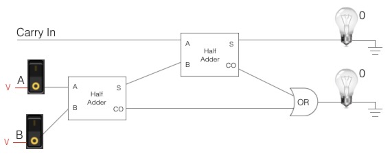
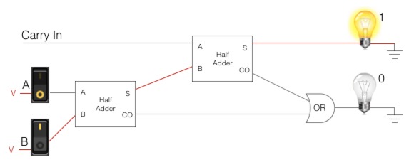
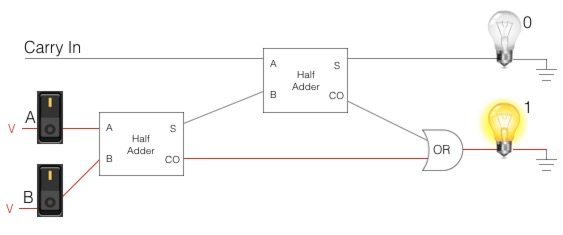
This is where the full adder comes in:
- It has 3 inputs: A in, B in, carry in
- It has 2 outputs: sum, carry out
| A in | B in | Carry in | Sum out | Carry out |
|---|---|---|---|---|
| 0 | 0 | 0 | 0 | 0 |
| 1 | 0 | 0 | 1 | 0 |
| 0 | 1 | 0 | 1 | 0 |
| 1 | 1 | 0 | 0 | 1 |
| 0 | 0 | 1 | 1 | 0 |
| 1 | 0 | 1 | 0 | 1 |
You get WET when you swim. Stay DRY when you code.
Episodes
Total Lab Runtime: 01:53:22
- 1 Lab Introductionfree 02:20
- 2 Understanding Switch Logicfree 13:36
- 3 Introduction to Pseudocode and Truth Tablesfree 16:28
- 4 Understanding Gates – NOT Gatefree 10:10
- 5 Understanding Gates – AND Gatefree 15:07
- 6 Understanding Gates - OR Gatefree 10:33
- 7 Understanding Gates – XOR Gatefree 10:42
- 8 Understanding Gates – NAND Gatefree 07:10
- 9 Understanding Gates – NOR Gatefree 06:34
- 10 Basics of Memory Circuit – S-R Latchfree 04:41
- 11 Basics of the Adder Circuitfree 16:01
