Introduction to Pseudocode and Truth Tables
Lab: Basics of Data and Program Circuitry
Video Runtime: 16:28
Pseudocode is a technique for expressing code in a more natural language. It allows you to think through your code before writing it. Then the truth tables provide you with the switch (gate) states. You will use these states in your code too.
Your takeaways from this episode are:
- Pseudocode is a verbose human-readable expression of logic
- Truth table provides the expected state of the output for the given argument(s)
- Both tools build logical and analytical thought processes
- Both tools help you to visualize for problem solving
Study Notes
Pseudocode
What is pseudocode?
- Written way to express logic
- Verbose
- Human-readable
- Helps you to visualize for problem solving
Exploring the Process
How would you explain the following circuit’s state? Using the power flow, express how the light’s state is affected by the switch.
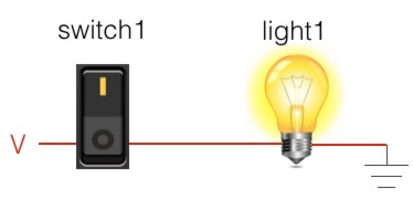
You would say:
- If switch1 is on,
- then light1 is on.
How would you express the same circuit when the switch is in the opposite state?
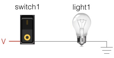
You would say:
- If switch1 is off,
- then light1 is off.
How can we combine these two expresses for both states into one if/then statement?
if ( switch1 )

then light1()
What is a truth table?
- Logic table
- Shows the state (true or false) for given argument(s)
- Builds your logical thought processes
- Helps you to visualize for problem solving
Exploring the Process
The process is to convert the states of a circuit in all of its iterations within a logical state table.
- Show the circuit in all conditions.
- Express the states for each input and the output for each circuit.
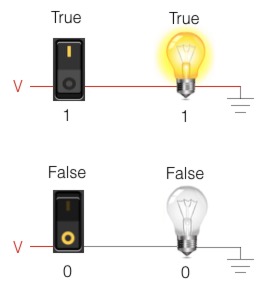
| Switch | Light bulb |
|---|---|
| 1 | 1 |
| 0 | 0 |
When given additional outputs the process remains the same.
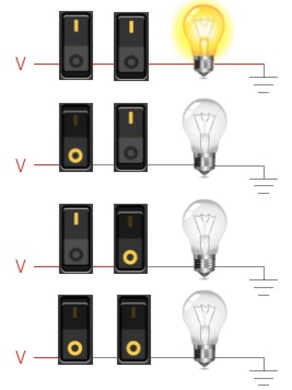
| Switch 1 | Switch 2 | Light bulb |
|---|---|---|
| 1 | 1 | 1 |
| 1 | 0 | 0 |
| 0 | 1 | 0 |
| 0 | 0 | 0 |
| Circuit | 0 | 1 |
|---|---|---|
| 0 | 0 | 0 |
| 1 | 0 | 1 |
What about a more condensed version of the truth table? Most truth tables are expressed in a more condensed format.
- The first row is the first switch (input).
- The first column is the second switch (input).
- The expected output is found by comparing the column and row for the given input states.
For example, if the first input is true and the second input is true, then you go to the last column and last row to find the state, which is 1.
Code. Eat. Code. Sleep. Dream about Code. Code.
Episodes
Total Lab Runtime: 01:53:22
- 1 Lab Introductionfree 02:20
- 2 Understanding Switch Logicfree 13:36
- 3 Introduction to Pseudocode and Truth Tablesfree 16:28
- 4 Understanding Gates – NOT Gatefree 10:10
- 5 Understanding Gates – AND Gatefree 15:07
- 6 Understanding Gates - OR Gatefree 10:33
- 7 Understanding Gates – XOR Gatefree 10:42
- 8 Understanding Gates – NAND Gatefree 07:10
- 9 Understanding Gates – NOR Gatefree 06:34
- 10 Basics of Memory Circuit – S-R Latchfree 04:41
- 11 Basics of the Adder Circuitfree 16:01
