Understanding Gates – AND Gate
Lab: Basics of Data and Program Circuitry
Video Runtime: 15:07
Just like in software, the AND gate turns on the output when both inputs are in an on state.
Your key takeaways are:
- AND works the same in circuitry as it does in code
- AND Gate (or
&&in code) work in “series” - Both input states must be “true” in order for the circuit to compute as “true”
Study Notes
AND Gates are inputs wired in series, meaning that both inputs must be in an “on” state for the output to be “on.” Logically you can use pseudocode to visualize the gate’s process:
if ( this AND that ) then do something
Using the if statement, if both of the states on either side of the AND operator are true, then the if evaluates to true and the then portion of the block will be executed.

Truth table
The following truth table is more verbose, giving you the states based upon the input and output listed on the top row.
| Switch 1 | Switch 2 | Light bulb |
|---|---|---|
| 1 | 1 | 1 |
| 1 | 0 | 0 |
| 0 | 1 | 0 |
| 0 | 0 | 0 |
This truth table is more concise and indicative of what you would see in books and on other sites. You read it like this:
- The top row is for input 1
- The first column if for input 2
Therefore, to see what state the AND Gate sets for the output when input 1 is 0 and input 2 is 1, you would do the following:
- Go to the second column which is the 0 state for input 1.
- Then move down the column to the bottom row, which is input 2.
- The state of the output then is 0.
| AND | 0 | 1 |
|---|---|---|
| 0 | 0 | 0 |
| 1 | 0 | 1 |
Relay Logic
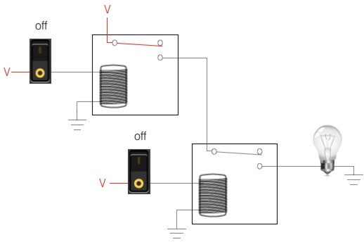
The relay logic in the image below shows you two separate relay circuits which are wired in series through the contacts within the relay. The switches are simulating the input signal feeding into the relay’s coil.

When the input is “on”, the relay coil is energized, which turns the relay to an “on” state. The contact within the relay is pulled into the “on” state” via magnetism.
When both inputs are “on”, then both relays are “on.” This means power can flow from the voltage source through the first relay’s contact, down the wire (which is the AND), through the second relay’s contact, to the output, and then to ground. The light will then turn “on.”
Let’s picture this in pseudocode:
if ( input1 AND input2 ) then turn on the light
If input1 and input2 are both “true”, the if evaluates to true which fires whatever is within the then code block.
Truth table
The following are two different versions of a truth table.
This table is more verbose, giving you each state in relationship to the inputs and outputs listed at the top.
| Switch 1 (input 1) | Switch 2 (input 2) | Light bulb (output) |
|---|---|---|
| 0 | 0 | 0 |
| 1 | 0 | 0 |
| 0 | 1 | 0 |
| 1 | 1 | 1 |
This truth table is more concise. The first column represents the second input and the top row is the first input. The middle section of the table represents the expected output from the AND gate.
| AND | 0 | 1 |
|---|---|---|
| 0 | 0 | 0 |
| 1 | 0 | 1 |
Quick tip
With an AND Gate, if the first input is in an “off” or false state, then the second input is not evaluated. Think about this in relationship to your code. If the first state is false, then the software evaluates the AND circuit to false and moves on to the next line of code.
Relating circuit to code
To help you understand the AND Gate circuit, let’s look at it in relationship to code. In the following PHP code block, the && is the same as a AND Gate.
| <?php | |
| function maybe_show_top_bar( $is_ok_to_show ) { | |
| if ( is_page() && $is_ok_to_show ) { | |
| showTopbar(); | |
| } | |
| } |

Hey... hey you... yes you!... Having a good time? Learning new things? Good!
Episodes
Total Lab Runtime: 01:53:22
- 1 Lab Introductionfree 02:20
- 2 Understanding Switch Logicfree 13:36
- 3 Introduction to Pseudocode and Truth Tablesfree 16:28
- 4 Understanding Gates – NOT Gatefree 10:10
- 5 Understanding Gates – AND Gatefree 15:07
- 6 Understanding Gates - OR Gatefree 10:33
- 7 Understanding Gates – XOR Gatefree 10:42
- 8 Understanding Gates – NAND Gatefree 07:10
- 9 Understanding Gates – NOR Gatefree 06:34
- 10 Basics of Memory Circuit – S-R Latchfree 04:41
- 11 Basics of the Adder Circuitfree 16:01
