Understanding Gates – XOR Gate
Lab: Basics of Data and Program Circuitry
Video Runtime: 10:42
The XOR in software can be confusing. Let’s look at it in circuitry to understand how it works.
Your key takeaways from this episode are:
Study Notes
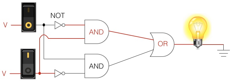
An XOR Gate is a combination of the following gates:
- two NOT Gates
- two AND Gates
- one OR Gate

Each input is wired to one leg of each AND with one of those legs going through a NOT Gate first before the AND. The NOT leg provides an inverse state of the input’s state.
Each AND Gate output wires to one of the inputs into the OR Gate. Therefore, either AND Gate can be “on” for the circuit to be “on.”
Remember it like this:
- If both states are not the same, then do something
Pseudocode
To help you visualize what is happening in the XOR Gate, let’s use pseudocode.
if( input1 XOR input2 ) then turn on the light
If input1 and input2 are different states, then the if statement evaluates to true and the then block executes. However, if the inputs are the same state, then the if statement evaluates to false.
Truth tables
| Switch 1 | Switch 2 | Light bulb |
|---|---|---|
| 0 | 0 | 0 |
| 1 | 0 | 1 |
| 0 | 1 | 1 |
| 1 | 1 | 0 |
Here is the condensed version of the truth table:
| XOR | 0 | 1 |
|---|---|---|
| 0 | 0 | 1 |
| 1 | 1 | 0 |
Note the final line on the truth table. This is the key difference between an OR Gate and an XOR Gate.
There’s a time to code and …. yup, that sums it up.
Episodes
Total Lab Runtime: 01:53:22
- 1 Lab Introductionfree 02:20
- 2 Understanding Switch Logicfree 13:36
- 3 Introduction to Pseudocode and Truth Tablesfree 16:28
- 4 Understanding Gates – NOT Gatefree 10:10
- 5 Understanding Gates – AND Gatefree 15:07
- 6 Understanding Gates - OR Gatefree 10:33
- 7 Understanding Gates – XOR Gatefree 10:42
- 8 Understanding Gates – NAND Gatefree 07:10
- 9 Understanding Gates – NOR Gatefree 06:34
- 10 Basics of Memory Circuit – S-R Latchfree 04:41
- 11 Basics of the Adder Circuitfree 16:01
