Understanding Gates – NOR Gate
Lab: Basics of Data and Program Circuitry
Video Runtime: 06:34
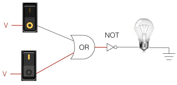
The NOR Gate inverts the output of the OR Gate. Let’s see how it’s done in this episode.
Your key takeaways are:
- NOR has an inverter after the OR Gate
- Opposite output state as the OR Gate
- If both input states are false, then the NOR output computes to true
- Else it’s false
Study Notes
What makes the output of an OR Gate true? Since it runs in parallel, if one or the other state is true, then the output is true.
So, for a NOR Gate, if both states are false, then do something.
Let’s compare the two:
OR Gate
| Switch 1 | Switch 2 | Light bulb |
|---|---|---|
| 1 | 1 | 1 |
| 0 | 1 | 1 |
| 1 | 0 | 1 |
| 0 | 0 | 0 |
Here is the condensed OR gate truth table:
| OR | 0 | 1 |
|---|---|---|
| 0 | 0 | 1 |
| 1 | 1 | 1 |
NOR Gate
| Switch 1 | Switch 2 | Light bulb |
|---|---|---|
| 1 | 1 | 0 |
| 0 | 1 | 0 |
| 1 | 0 | 0 |
| 0 | 0 | 1 |
Here is the condensed NOR gate truth table:
| OR | 0 | 1 |
|---|---|---|
| 0 | 1 | 0 |
| 1 | 0 | 0 |
The NOR Gate is the opposite state of the OR Gate. If you know how an OR Gate works, then you know how the NOR gate works!
What gives us the opposite state of an OR Gate? Hopefully, you remember it from the NAND Gate: an inverter!

When was the last time you got out of your chair and stretched? Just saying…
Episodes
Total Lab Runtime: 01:53:22
- 1 Lab Introductionfree 02:20
- 2 Understanding Switch Logicfree 13:36
- 3 Introduction to Pseudocode and Truth Tablesfree 16:28
- 4 Understanding Gates – NOT Gatefree 10:10
- 5 Understanding Gates – AND Gatefree 15:07
- 6 Understanding Gates - OR Gatefree 10:33
- 7 Understanding Gates – XOR Gatefree 10:42
- 8 Understanding Gates – NAND Gatefree 07:10
- 9 Understanding Gates – NOR Gatefree 06:34
- 10 Basics of Memory Circuit – S-R Latchfree 04:41
- 11 Basics of the Adder Circuitfree 16:01
